
As we've alluded to in other articles, making your own grips from cork rings is an important part of building a custom rod. "Staying with the cost-effective strategy, I decided to try and build my own cork lathe using common materials and a drill." Read more of Jon Jenkin's article.
Preformed grips are ok, but having the ability to turn your own grips really enforces the notion
of a "custom built" rod.
Bill of Materials
| 1 | 1/4" threadrod, 36" long, cut in half |
| 1 | 2x4"6 or 8 feet long, whatever is cheapest, or scrap 2x4 layingaround the house |
| 4 | 1/4"nuts |
| 4 | 1/4"wingnuts |
| 8 | 1/4"washers, O.D. doesn't really matter, 5/8" will work fine |
| 3 | Stanleygarage door casters, get ones with plastic wheels or coatedsteel (doesn't mar blank) Try a garage door installation company,many times have extras laying around and will give you themfor free. |
| 3 | 1/2"nylon spacers, I.D. to fit shaft of garage door caster |
| 1 | 3/8"drill bit (for threadrod holes) 1/4" will work, but will haveto drill exact |
| 1 | drillbit to drill holes for garage door casters |
| 3 | smallhose clamps that will tighten down on garage door caster'sshafts |
| 1 | skillsaw or table saw. |
| 12 | orso 2 1/2" or 3" wood screws |
| 1 | 4"hose clamp |
The craft of building rods is a rewarding, creative and challenging venture. When I began building rods, I did it as a means to save money. I built my first rods from kits, then went on to building "hand-picked" components, but still using performed cork grips. Don't take it wrong, there is absolutely nothing wrong with using the many high quality preformed grips out there, but I wanted to try shaping my own. Little did I know that in order to build many rods, a few choice pieces of equipment would make the process easier and allow it to be a "truly" custom rod. But, some of these items defeated the concept of cost saving. So staying with the cost-effective strategy, I decided to try and build my own cork lathe using common materials and a drill. The following article will hopefully spark ideas and motivate some to try turning their own cork. I have said for some time now that I need to go back and rebuild the stand to make it "better", but the crude example I am showing you today has provided me a good many handles and I just have been too busy building rods to redo anything now.
FIGURE 1:
Before we start, I must mention that I had the luxury of mounting my stand on an unfinished wall. This allowed me to attach my stand arms directly to the studs. If you are dealing with a finished wall, simply modify this by attaching a 2x4 flat to the wall where the drill stand and the wheel stand will be. Then simply attach the arms to the side of the 2x4. Also, depending on the size of garage door casters you get, the dimensions may vary somewhat. Remember, you are building this for YOUR preference and requirements, so be creative and simply do what works.

First, cut 3 pieces of 2x4 about 9" in length (I cut mine12" to allow for the unfinished wall). Now, take one of those 2x4s and cut it lengthwise to end up with two 2x2 pieces. Now, cut a length of 2x4 6" long and cut it lengthwise as above to get two 2x2 pieces. If you have a finished wall, take two 2x4s about 16" and mount them in vertical manner flat against the wall where the lathe stand and drill stand will be. Don't forget to consider the appropriate working height, I stand while I turn grips, but if you will be sitting, mount appropriately. I find that about chest high works best.
Now, mount the 12" arms about 11" apart (up and down) from each other to the side of the cork stand 2x4s you just attached to the wall with wood screws. Use two screws each to prevent them from twisting and use a level to mount them straight out. See the picture, to clarify what I am writing.
Pictures are truly worth many words.
FIGURE 2:
Now on the top arm take your 3/8" drill bit and drill a hole (as straight as possible) about 1-2" in from the tip. Take one of the 18" threadrods and insert through hole till it touches the bottom arm. Take a level against the threadrod to ensure it is plumb, this marks the location to drill the bottom hole. Drill bottom hole. Do the same about 4 inches in from the first location.
Now, with threadrodsremoved, take one of the 6" "caster holders" (can't think of a betterterm) and set it on the bottom arm, even it up on all sides. Place thethreadrods down through the top arms again, plumb, and mark your holesfor the holders. Do this for both holders. All this is just an easyway to align all the holes in the contraption. If you have a drill press,you can do it all there a little easier. But, I don't, so I didn't.
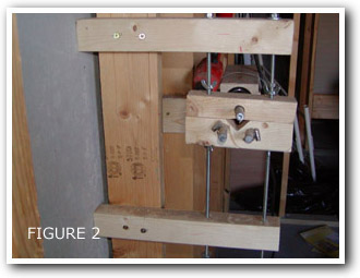
Now you have allyou holes aligned (hopefully) and drilled. Let's focus on mounting thecasters in their holders.
It took a littletrial and error because I couldn't drill the holes at the very edgeof the holders or the wood would bust out. So, for the top holder, centerdrill a hole to accommodate the caster shaft. On the bottom holder,take the two casters and center them horizontally on the holder. Movethem in till the actual wheels barely overlap just by "eyeing it" (seepic)
FIGURE 3:
Mark the locations and drill them out. (you'll notice my crudeness that the wheels are not perfectly straight through the wood, try to do better than I did, but it works fine either way) We can't leave it like this or you the wood on the top of the holder will interfere with the blank or mandrel, so put the casters in their holes and roughly mark a V-notch (see photo below) to allow clearance of a blank or mandrel.

FIGURE 4:
Remove casters and cut this notch (very carfully!!) with skill saw or table saw. We are just about done, but one more thing to do. Since the wheels overlap we can not have them on the same plane. Here is where the nylon spacers come into play. It is important to have the wheels overlap or you will be unable to bring them all into contact with a rod or mandrel, they would tough each other before the rod. So on the bottom holder, place two spacers on one caster shaft before inserting into the holder, no spacer on the other caster. (see pic below) On the top holder, place one spacer on the shaft. Once all the casters are inserted with appropriate spacers, take your three hose clamps on the back side to hold them in place. See picture above for clarification.

FIGURE 5:
We are ready for assembly. Take one of the threadrods through the top arm place a wingnut and washer facing down and screw up the thread rod quite a ways. Now take threadrod through both holders and place a wingnut and washer facing up and thread a way. Now take threadrod through bottom arm. Adjust the wingnust and holders to where you have a couple of inches of threadrod sticking out of the top and bottom arms. Attach washer and nut. Handtighten, you don't want to tighten too much or you will force the arms out level. Repeat for other threadrod. DONE! Adjustment is as simple as loosening and tightening wingnuts around the holders to get the appropriate position.

FIGURE 6:
(Drill Stand) Wewww! The hard part is over. Now comes the drill stand.
Take the two 2x4s9" long that you cut earlier. Simply mount them upright with the topsbeing on a plane about 3" below the center of your lathe stand. Mountthem level and on each side of the 2x4 mounted to the wall (if workingwith finished wall). Now, if you are working with a finished wall, the2x4s will be about 3 1/2" apart, where mine are 1 3/4" apart. This doesn'tmatter. Now cut a 2x4 the length or longer of your drill. Now mountit flat on top of the two arms you just mounted. Only screw it downon one 2x4 and center in plane with your casters. The reason for onlyscrewing down to ONE 2x4 is this allows you to slide your 4" hose clampand drill back and forth along the 2x4 to adjust for varying lengthsof grips, mandrels and blanks. Slide your hose clamp over the end ofthe 2x4 your did not screw down, get your drill and place in the hoseclamp. Tighten. Some models of drills might require an additional 3"or so hose clamp to secure it right behind the chuck, mine didn't. You are ready toturn. Chuck up a mandrel, threadrod, or blank. Adjust your holders tosecure it on a level plane (don't forget to place a few turns of tapearound your blank where the wheels touch it and around the butt sectionwhere it chucks into the drill). I made a neat little arbor to allowme to mount blanks to my drill for blanks too big for my chuck.

FIGURE 7:
(Chuck Arbor) I went and got #6 x 2 1/2" machine screw with as small a washer that would fit and two nuts. I found some conical rubber stoppers (at Lowes in the sink fixture plumbing stuff). I center drilled the stopper and put the screw through the middle, put washer and two nuts on. Tighten. Chuck the screw into the drill by the threaded end and using coarse sandpaper, turn the stopper down until it will fit inside the blank. Now, insert assembly into blank and begin tightening nut until the rubber expands and grips the inside of the blank. Tighten second nut to prevent from first one coming loose during turning. Chuck into drill again and turn. Works great! Note: I just found some very small fuel line hose that I am going to try instead of the stopper. This just saves a step in turning the stopper down. Got it a Ford dealership, only need a few inches of it, they ought to give it for free if you ask nicely.
That's it! Thisall sounds really complicated, but it is not. The only thing I mightsuggest to do differently is use larger threadrod for the lathe stands.The 1/4" bends fairly easily and larger size might remedy this. I havean additional lathe stand I built for turning long sections of blanksto prevent whipping. I typically turn all my handles on threadrod, thenglue to the blank, but sometimes a little touchup is needed. A cheapway to prevent whipping is find the right size towel, drape over thetip section and tape the ends of the towel together. If you get theright weight towel it will eliminate most of the severe whipping.

Elrod (Jon Jenkins)
cranecreekrods@hotmail.com
- Log in to post comments


Actuallly Wardman is
Actuallly Wardman is not necessarily wrong. Many dimmers are rheostat designs (you can find them by web-surfing). There was a time when they all were, but rheostats don't reduce power consumption (they only route a portion of the current away from the appliance load), so many dimmers are instead now done with solid state components that "pinch off" the current). Yes, true, you may have to be careful which one you buy...and you have to pay close attention to the current rating of the rheostat, even if you choose a rheostat fan motor control. Clearly Wardman has tried it successfully (or he wouldn't have recommended it), so he picked the right one. (And if you pick the wrong one, I think you don't really risk burning up your drill motor...but the rheostat can overheat and fail (and could get hot enough to start a fire, for example if you "control" your single-speed drill down to a really slow speed to use as a rod dryer, and then walk away and let it run unsupervised).
You ALWAYS have to check current ratings on anything you use, for that matter.
I work as a electric
I work as a electrical contractor and the information you have printed here is wrong and could be dangerous! Dimmers are made to be used on incondecent lamps and not for motor loads. If you want to make what you are suggesting here, you must use a fan speed control which is a reostat to slow down a motor. An incondecent dimmer could overheat and burn up if used on a motor load!
Add true control to
Add true control to this entire project with a home made speed control. Rapid-speed blank whipping is the last thing you want.. but the first thing you'll get with the average hand drill, so here's an easy fix. For less than ten bucks go to your HD or Lowes and buy a lighting dimmer switch just like the one in your dining room (push = on/off, twist to dim). Buy a plastic single gang switch box and an extenstion cord (the cord should be the same size and durability as the cord on your drill). Take the extenstion cord and cut it in half. Insert the cut end of the pronged piece into the switch box and wire it as the source of power to the dimmer. Insert the cut end of the outlet piece into the switch box and wire it to the dimmer as the output (normally goes to your dining room lighting). Secure the dimmer in the PVC electrical switch box, add a switch cover for style and safety AND YOU'RE DONE. Set the dimmer gizmo next to your lathe widgit, plug your drill into the dimmer with the drill switch-lock ON. Tap the dimmer to life and slowly turn up the juice till you are comfortable with the speed. It is also is a great panic button to stop things NOW if something goes wrong. BONUS: Its also a speed control for your wrapper or dryer if you are just a beginner without a lot of different high end motors. Thats a Wrap., dave w